

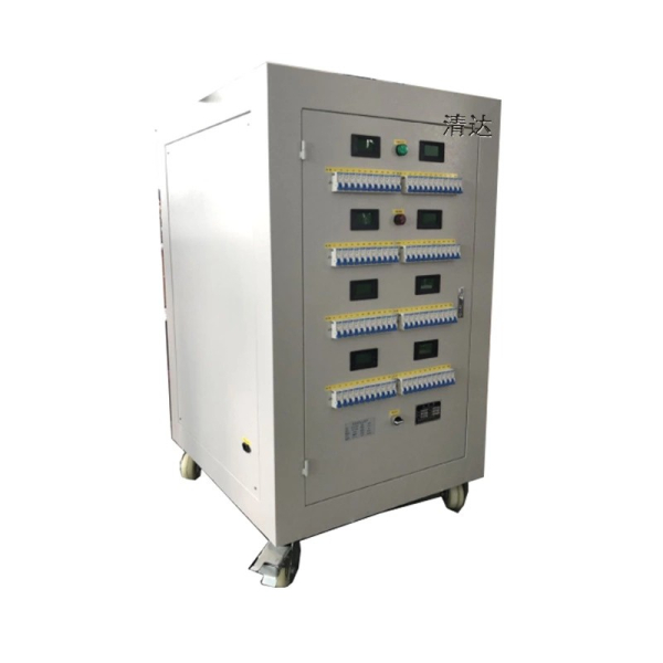
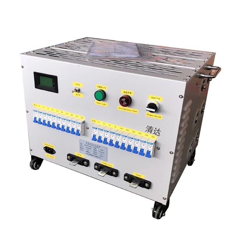
Qingda A Load Resistor Box is an electrical testing device that uses resistor elements to simulate actual power consumption conditions of electrical equipment. By converting electrical energy into controlled heat during operation, it allows engineers to evaluate output stability, load capacity, overload response, protection functions, and long-term operating reliability.
Unlike braking resistor solutions that are mainly designed to absorb regenerative energy from motor deceleration, a load resistor box functions as a controllable test load for verifying the performance of power sources and power conversion equipment.
Product Structure and Working Principle
The internal resistor assembly consists of multiple corrugated resistor elements arranged through series and parallel connections to achieve different load configurations. Independent load sections allow users to adjust testing conditions by switching different resistor groups without changing the overall hardware structure.
The working process can be described as:
Power Equipment Output → Load Resistor Box Input → Resistor Load Consumption → Performance Data Evaluation
The enclosure is manufactured with aluminum-zinc coated steel sheet, providing mechanical protection, efficient heat dissipation, corrosion resistance, and convenient installation. A dedicated terminal block is integrated for external electrical connection, while optional forced air cooling is available for applications requiring continuous high-power operation.
Product Specification
| Parameter | Specification |
|---|---|
| Power Range | 1KW-30KW |
| Working Voltage | ≤1200V |
| Resistance Range | 0.01Ω---1KΩ |
| Resistance Tolerance | ±3/±5/±10 |
| Protection Grade | IP20/IP23 |
| Temperature Coefficient | ≤300 ppm/℃ |
| Flame Retardant Grade | UL 94V-2 |
| Standard Compliance | GB-5792 |
Designed for Power Equipment Testing
UPS Performance Verification
The equipment provides controlled load conditions for verifying UPS rated output capability, overload response, voltage stability, and long-duration operating performance. By applying different load levels, engineers can evaluate UPS behavior under conditions that more closely represent actual operating requirements.
Generator Testing
As an artificial electrical load, the equipment can be used to verify generator capacity before commissioning or during scheduled maintenance. Typical applications include diesel generator testing, backup power system inspection, and factory acceptance testing, helping confirm output performance under defined load conditions.
Inverter and Power Supply Testing
The controlled resistive load allows engineers to evaluate output current capability, thermal performance, protection functions, and long-term operating reliability of inverters and power supplies. Adjustable load conditions also support testing at different stages of equipment operation.
Energy Storage System Testing
The system provides controlled discharge loads for battery systems, PCS equipment, and energy management systems, allowing engineers to assess discharge performance and operating stability under specified electrical conditions.
Main Features
Independent Load Section Control
The internal circuits are divided into multiple independent load groups, allowing power to be adjusted progressively according to the required test profile. This configuration supports flexible load combinations, repeatable testing conditions, and easier fault isolation when individual sections require inspection.
Multiple Operating Conditions Simulation
The system can reproduce different load conditions, from light-load operation through full-load and short-term overload testing, allowing engineers to evaluate equipment performance across a broader operating range.
| Test Condition | Purpose |
|---|---|
| Light Load | Verify low-power operation |
| Half Load | Check medium-load performance |
| Full Load | Confirm rated capacity |
| Overload | Evaluate protection capability |
AC and DC Compatible Design
The integrated terminal structure can be configured for both AC and DC testing applications, providing greater flexibility when testing different types of power equipment. With a maximum working voltage of 1200V, the system can accommodate a range of industrial power testing requirements without requiring changes to the basic resistor structure.
Installation Guide
1. Confirm Specification
Before installation, select the appropriate power rating, resistance value, and protection grade according to the tested equipment output power, required test conditions, and installation environment. Proper specification matching is essential for safe energy dissipation during testing.
2. Check Equipment Condition
Inspect the enclosure, terminal blocks, and cooling system before installation to confirm that the equipment is intact and ready for operation. Any visible damage or abnormality should be addressed before electrical connection.
3. Select Installation Location
Install the equipment in a well-ventilated location with sufficient clearance for heat dissipation. The installation area should be kept away from flammable materials, restricted airflow conditions, and excessive humidity that could affect safe operation.
4. Fix the Equipment
Use the mounting holes provided on the enclosure to securely install the unit on the floor or designated test platform. The mounting structure should be suitable for the equipment weight and operating conditions.
5. Electrical Connection
Connect the output terminals of the tested equipment to the load input terminals according to the supplied wiring diagram. For DC applications, polarity must be confirmed, while all terminal connections should be properly tightened and connected with cables suitable for the expected current.
6. Testing Operation
After verifying the complete electrical connection, begin testing at a low load level and gradually increase the active load sections according to the test procedure. During operation, monitor resistor temperature and other relevant operating conditions to ensure the equipment remains within the specified range.
Performance and Reliability Testing
Qingda Load Resistor Box is designed for long-duration electrical testing and undergoes electrical and mechanical performance verification before delivery. Testing focuses on resistance characteristics, electrical safety, mechanical integrity, and stable operation under different load conditions, helping ensure reliable performance in industrial testing environments.
Electrical Characteristics
| Electrical Characteristics | Test Conditions | Performance |
|---|---|---|
| Dielectric Strength | 2500VAC/50Hz/60S | Leakage current ≤10mA |
| Insulation Resistance | 1000VDC | Insulation resistance ≥100MΩ |
| Short-Time Overload | 10 times rated power 5S | No visible damage |
| Long-Term Load Life | Cyclic operation (Discharge 10S, Interval 90S) | More than 9000h |
| Steady-State Damp Heat | 40℃±2/90%-95%RH/100h | △R≤±(1%R+0.05Ω) |
| Rapid Temperature Change | -55℃, 55℃, 155℃ each for 15 minutes, 5 cycles | △R≤±(2%R+0.05Ω) |
| Heat Resistance | 350℃/2h | No obvious discoloration or damage |
| Temperature Coefficient | Comparison between resistance under rated load and static resistance | Less than 300 ppm/℃ |
| Flame Retardancy | 10 times rated power for 5 minutes | Red glow but no flame |
Mechanical Characteristics
The enclosure structure is designed to withstand transportation, installation, and industrial operating environments. Mechanical tests ensure the terminal system and housing structure maintain reliability during long-term use.
| Mechanical Characteristics | Test Conditions | Performance |
|---|---|---|
| Terminal Strength | 45N/30S | No loosening or visible damage |
| Vibration Resistance | 5-200Hz、1g、98m/S² | No visible structural damage |
| Soldering Heat Resistance | Lead terminal immersed in 350±5℃ solder for 3S | △R≤±(1%R+0.05Ω) No visible external damage, clear marking |
| Solderability | Terminal immersed in 235±5℃ solder for 5S | Terminal surface solder coverage ≥95% |
Load Simulation Capability
Flexible Load Configuration
Different testing requirements require different load conditions. The internal resistor groups can be configured into multiple independent sections, allowing users to adjust the applied load according to actual test procedures.
Typical configurations include:
| Load Mode | Testing Purpose |
|---|---|
| Low Load | Verify startup performance and low-power operation |
| Medium Load | Evaluate partial output capability |
| Full Load | Confirm rated power performance |
| Overload Load | Check protection response and system stability |
This sectional design allows engineers to perform multiple tests with one unit instead of preparing several fixed-value load devices.
Continuous Operation Capability
For production testing, laboratory verification, and equipment reliability evaluation, load equipment often needs to operate under continuous and demanding conditions. Dufew Load Resistor Box is designed with stable resistance performance, optimized heat dissipation structure, independent resistor grouping, and optional forced air cooling to support long-duration high-power testing.
This design makes it suitable for applications such as factory aging tests, generator performance verification, UPS reliability evaluation, and power supply testing, where consistent load conditions are required.
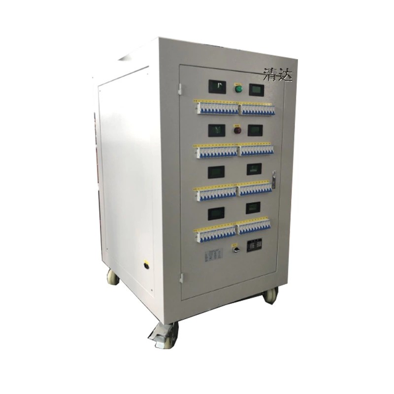 Resistance box (decade resistance load box) is a configurable resistance testing & loading equipment independently manufactured by Guangdong Qingda Electronic Technology Co., Ltd. Our product line covers precision decade resistance box for laboratory calibration and high‑power load resistance box for industrial load testing.
Adopting high‑quality wire‑wound, metal film or non‑inductive resistors inside, the resistance box realizes stepless or step‑by‑step resistance adjustment. It is widely used for battery discharge test, generator/UPS/inverter load simulation, equipment aging test, circuit calibration, electronic experiment and fault simulation. We support custom power, resistance range, cooling mode (air‑cooled / water‑cooled), control mode and cabinet size for special project requirements. All products comply with RoHS standard.
Key Features
- Two main types: Precision decade resistance box & high‑power load resistance box
- Wide power coverage: 0‑100kW (custom higher power available); AC & DC dual‑use
- Multiple adjustment modes: rotary switch step adjustment, stepless adjustable, digital intelligent control
- Cooling solution options: natural air cooling, forced air cooling, water cooling
- High stability, low temperature drift, good overload resistance, safe cabinet‑type enclosure
- Support OEM / ODM: custom resistance range, cabinet dimension, terminal, display function
- Strict factory testing, long service life, RoHS compliant
Typical Applications
- Generator, UPS, inverter, rectifier output load simulation & aging test
- Battery pack discharge test, capacity detection, power equipment commissioning
- Laboratory circuit calibration, multimeter & instrument verification, electronic teaching experiment
- Industrial equipment debugging, relay protection test, energy‑storage system simulation
- Aviation, new‑energy, power system, railway equipment testing scenarios
About Manufacturer
Guangdong Qingda Electronic Technology Co., Ltd is a professional manufacturer engaged in power resistors, high‑voltage resistors and complete resistance load boxes. We provide standard and customized resistance box solutions with full‑range quality inspection. Welcome to send your technical specifications for quotation and sample consultation.
resistance box, decade resistance box, load resistance box, adjustable resistor cabinet, AC DC resistance load box, generator test load box, Guangdong Qingda Electronic